Supply/Return Air Registers, Grilles, and Fresh Air Grilles
Dimension Data
Supply Air Registers
(SAR-DD-H) Supply Air Register Horizontal and Vertical
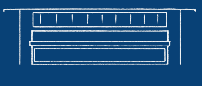
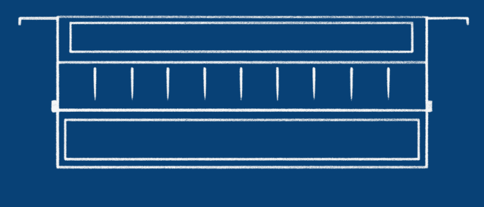
Supply Registers (Double Deflection):
Design: Equipped with two rows of adjustable blades, one horizontal and one vertical.
Function: Offers enhanced control over air direction, allowing adjustments both vertically and horizontally.
Application: Suitable for spaces requiring precise and versatile air distribution, especially where multi-directional airflow is needed.
(RAG-DD-V) Supply Air Register Horizontal and Vertical
Return Air Grilles (Double Deflection):
Design: Feature two sets of blades, both horizontal and vertical, which can be fixed or adjustable.
Function: Allows modest control over the direction of incoming return air in two planes.
Application: Useful in scenarios where there’s a need to slightly adjust the direction of return air, often in more complex HVAC setups.
In Summary
Double-deflection units offer nuanced control in two planes — ideal for spaces needing precision and multi-directional airflow management
(SAR-SD-H) Supply Air Register Horizontal and Vertical
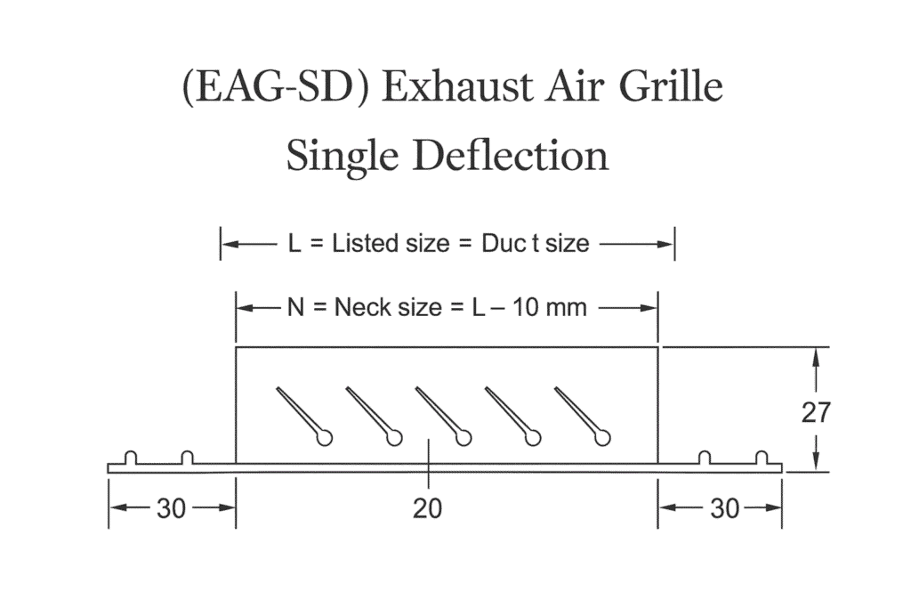
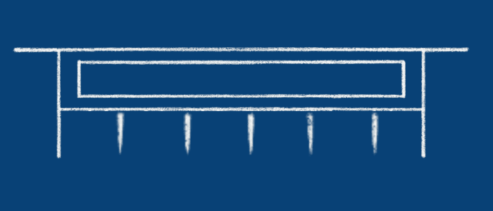
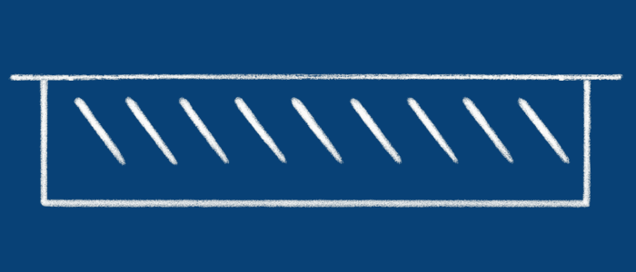
Supply Registers (Single Deflection):
Design: Feature a single row of adjustable blades, which can be either horizontal or vertical.
Function: Allows for control of airflow direction in one plane, either horizontally or vertically, but not both.
Application: Ideal for targeted air distribution in specific directions, such as directing air along the ceiling or down a wall.
(RAG-SD-V) Supply Air Register Horizontal and Vertical
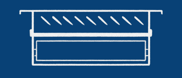
Return Air Grilles (Single Deflection):
- In Summary
Single-deflection units (both supply registers and return air grilles) provide direction control in one plane, making them suitable for straightforward air distribution tasks.
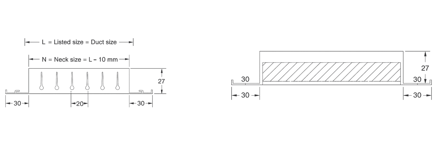
Exhaust Air Grilles – 45° Fixed Blades:
Blade Design: Grilles with fixed blades at a 45-degree angle, set at a fixed angle to the face of the grille.
Material: Usually made from aluminum or stainless steel for durability and longevity.
Construction: Rigid construction, designed to provide efficient air passage and protection from rain/debris when used externally.
Exhaust Function: Efficiently remove air from spaces such as kitchens, bathrooms, industrial areas.
External Use: Prevents ingress of rain; maintains airflow.
Aesthetics & Directional Flow: Can be aesthetically pleasing and help direct air in a specific direction.
Models (Supply & Return Air Registers)
Double deflection Return Air Grille with individually adjustable front vertical and rear horizontal airfoil blades.
MODEL RAG-V

Double deflection Return Air Grille with individually adjustable front horizontal and rear vertical airfoil blades.
MODEL RAG-H
Double deflection Supply Air Register same as RAG-V but with an Opposed Blade Damper.
MODEL SAR-V
Double deflection Supply Air Register same as RAG-H but with an Opposed Blade Damper.
MODEL SAR-H
Return Air Grille with fixed horizontal blades with a 45° angle.
MODEL RAG-HF
Return Air Grille with individually adjustable vertical airfoil blades.
MODEL RAG-V

Return Air Grille with individually adjustable horizontal blades.
MODEL RAG-H

Return Air Register same as RAG-HF but with an Opposed Blade Volume Control Damper.
MODEL RAR-H
Air Stream Flow Assessment
THROW
The throws, as shown in the Deflection
diagram, are based on a Terminal Veloci-
ty of 0.25 m/s measured in the axis of the
jet. The throws for other Terminal Veloci-
ties can be obtained by using the Correc-
tion Factors chart below.
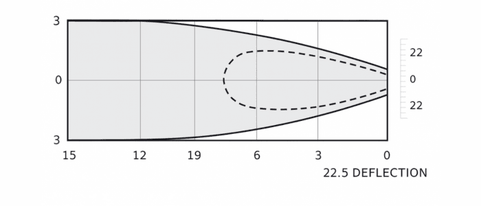
EXPANSION ANGLE
With the straight blade setting, the airflow is dis-
charged at an approximate expansion angle of
18° – 20°.
With the blade setting at 22° on both sides, the
expansion angle is increased and the throw is de-
creased. The expansion angle then becomes ap-
proximately 35°.
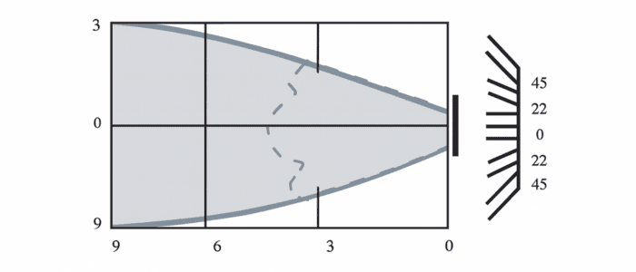
With the blade setting at 45° on both sides, the
expansion angle then becomes approximately
60°. For other data changes, refer to the Correc-
tion Factor chart below.
Correction Factors For Deflection
| Parameter | 22° (35° Angle of Discharge) | 45° (60° Angle of Discharge) |
|---|---|---|
| Lt. | x 0.77 | x 0.55 |
| Vk | x 1.15 | x 1.25 |
| pt | x 1.30 | x 1.60 |
| NR | + 3.00 | + 5.00 |
Air Stream Drop Assessment
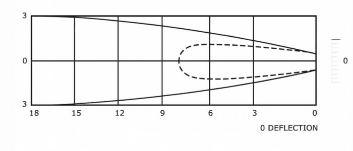
DROP
The data for Drop shown here is for a type of installation without a ceiling effect. The drop
due to the temperature differential is insignificant if there is a ceiling effect, and if the Ter-
minal Velocity at the opposite wall is at least 0.375 m/s. The drop due to the spread of the
airflow is always present.
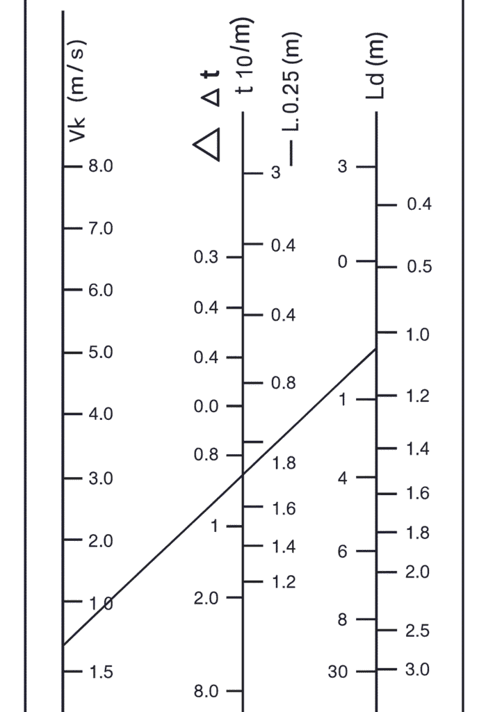
EXAMPLE
As shown in the Drop Chart, the throw at 0.25 m/s : Lt. =
6.0 m. Discharge velocity Vk = 3 m/s at -10° temp. diff.
METHOD
Connect the values for Vk and Lt. by a straight line. The
isothermal drop due to the spread can be read on the line of
the throw as : Ld. = 0.75 m.
On the middle scale, read the data for -10° temp. diff.
Ldx. = 1.45/1.65 m
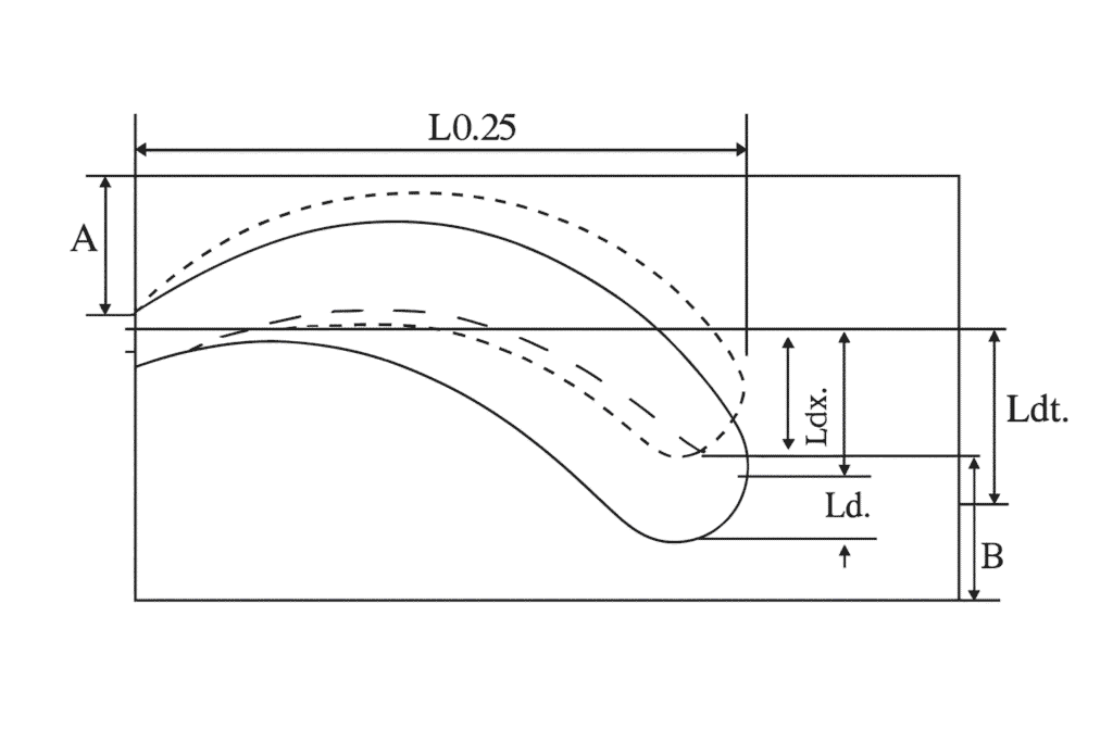
Total Drop:
Ldt. = Ldx. + Ld. = 1.45/1.65 + 0.75 = 2.4 m
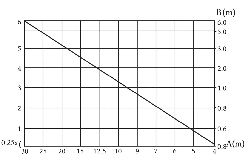
The drop can be corrected by setting an upward deflection
of 15° to 20°. The correction “B” of the drop must be
mounted at a distance “A” from the ceiling (0.6 mm
minimum).
A = 0.135 x L0.25 and B = 0.22 x L0.25
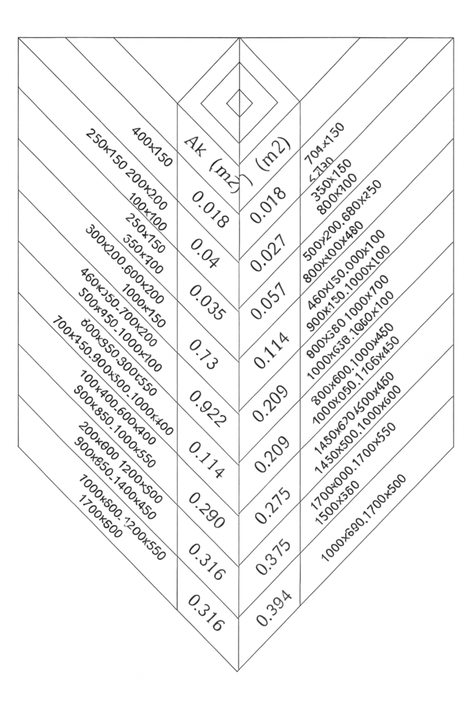
Ak Value Chart