
Linear Slot Diffusers
Introduction
ALUGRIDX Linear Slot Diffusers (LSD) are adjustable diffusers for use in ceilings as a feature or as an unobtrusive inlet/outlet unit giving either a vertical or horizontal air pattern. These slot diffusers can be supplied in 1 to 8 slot configurations, the units being butted together to form continuous lengths (if required).
Linear Slot Diffusers can be supplied with Hit & Miss Damper and Plenum Boxes (PB). Each diffuser slot contains an airflow-regulating damper under which is an airflow regulating vane which gives directional control to the discharged air. Alignment of the butting section is achieved by loose strips which engage in the slots provided for the purpose.
Linear Slot Diffusers are manufactured from extruded aluminium in a natural mill finish, while the face section will be available in a powder-coated/anodized finish.
Selection of Air Terminal Devices
The function of an Air Terminal Device (ATD) is to direct the incoming or exhaust air in such a way that comfortable conditions are maintained in the occupied zone of any conditioned space. Failure to choose a suitable ATD, especially that used for supply purpose, may well nullify all other efforts to achieve comfort conditions in a room. At the same time, the ATD should be selected to suit aesthetic requirements. It is necessary at the selection stage to choose the position (wall, ceiling, floor, or sill) of the ATD’s and the number, form, and type.
Consideration must be given to the occupancy of the conditioned space and the internal features, such as irregularities of surface, position of furniture, and any source of heat loss/gain.
Consideration should also be given to the method of fixing and to the finish of the ATD’s.
! No ATD can compensate for incorrectly designed duct entry conditions
Air from linear slot diffusers is a wide airstream (which can be taken as two-dimensional). The primary velocity is in proportion to the square root of the distance from the linear slot diffuser. There is little increase in the width of the airstream. This type of Air Terminal Device has a length-to-width aspect ratio of 10:1 or greater.
Throw from linear slot diffusers is taken to mean the distance from the device to the opposite wall.
Having taken into account the throw, drop (if applicable), and position of linear slot diffusers in the ceiling, airflow rate can be established per unit length (m) by number of slots of the ATD to meet the design criteria. Note should be taken of the noise and pressure characteristics.
To obtain the length of the slot diffuser, divide the total airflow rate per unit length (m). This total length can then be divided to suit the physical limitations and architectural requirements.
The number of slots and the width of the slot, i.e., S-16 or S-20 or S-25, can be determined. Note should be taken of the noise and pressure characteristics/data.
Single & Multi-Slot Airflow Adjustment

Flange/Assembly options
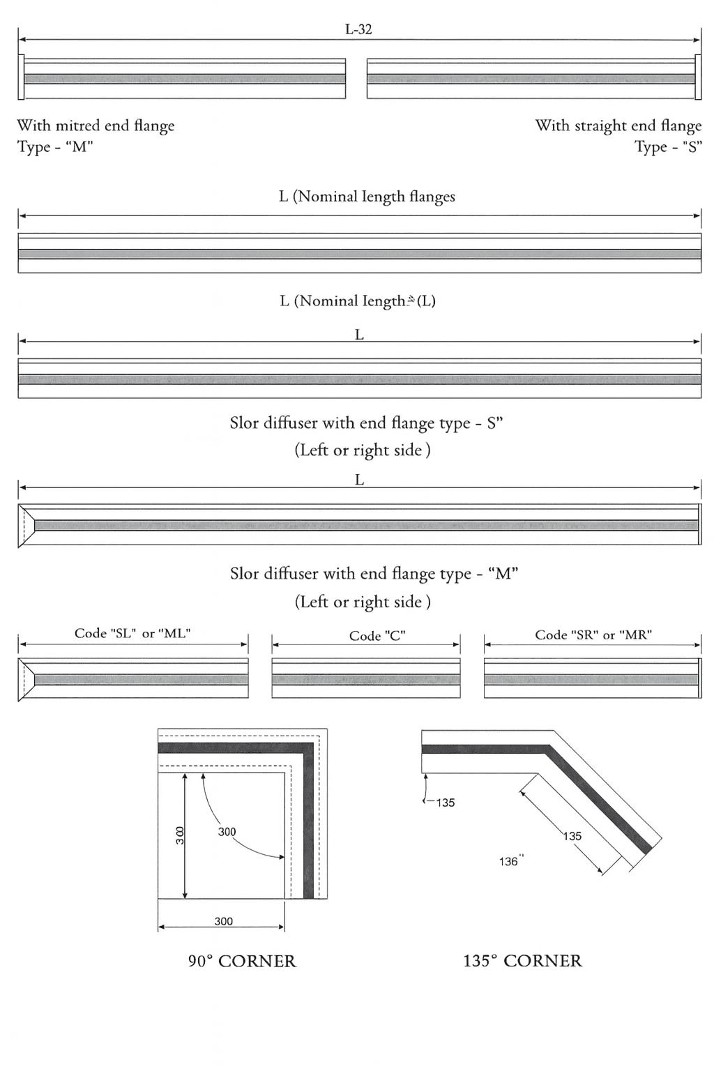
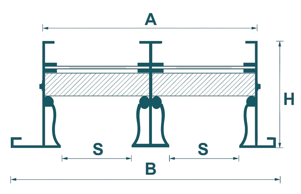
Dimension Data
SLSD
ALUGRIDX model SLSD is a Supply Linear Slot Diffuser with
Hit-&-Miss Volume Control Damper and Straightening Deflectors.
The Air Straightening Deflectors and Hit-&-Miss Damper are adjustable.
| Slots | Neck | Flange |
|---|---|---|
| 1 | 3.5 | 7.28 |
| 2 | 6.98 | 10.76 |
| 3 | 10.46 | 14.24 |
| 4 | 13.94 | 17.72 |
| 5 | 17.42 | 21.2 |
| 6 | 20.9 | 24.68 |
| 7 | 24.38 | 28.16 |
| 8 | 27.86 | 31.64 |
RLSD / ELSD
ALUGRIDX model RLSD / ELSD is a Return or Exhaust Linear
Slot Diffuser with a single Hit-&-Miss Damper (Optional).
The Hit-&-Miss Damper is adjustable from the face of the Linear Diffuser.
| Slots | Neck | Flange |
|---|---|---|
| 1 | 3.9 | 7.68 |
| 2 | 7.78 | 11.56 |
| 3 | 11.66 | 15.44 |
| 4 | 15.54 | 19.32 |
| 5 | 19.42 | 23.2 |
| 6 | 23.3 | 27.08 |
| 7 | 27.18 | 30.96 |
| 8 | 31.06 | 34.84 |
DLSD
ALUGRIDX model DLSD is a Dummy or non-active linear slot
diffuser with a blanking plate to replace Hit-&-Miss Damper.
ALUGRIDX Linear Slot Diffusers are available from 1–8 slots
(more than 8 slots are available on request) and two different slot
widths for low and high airflow requirements.
Coding:
• S-16 = 16 mm Slot Width
• S-20 = 20 mm Slot Width
• S-25 = 25 mm Slot Width
| Slots | Neck | Flange |
|---|---|---|
| 1 | 4.4 | 8.18 |
| 2 | 8.78 | 12.56 |
| 3 | 13.16 | 16.94 |
| 4 | 17.54 | 21.32 |
| 5 | 21.92 | 25.7 |
| 6 | 26.3 | 30.08 |
| 7 | 30.68 | 34.46 |
| 8 | 35.06 | 38.84 |
Technical Details
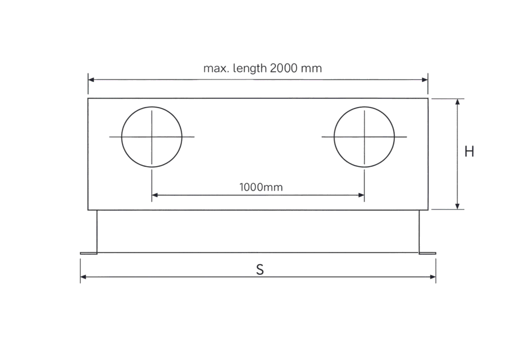
ALUGRIDX internally lined Plenum Boxes are used for even distribution of cool and dehumidified air over the linear surface of the slot diffuser with virtually no sound or turbulence.
ALUGRIDX Plenum Boxes are manufactured to cover the full range of Linear Slot Diffusers, i.e., from 1 to 8 slots.
To maintain rigidity, all joints Plenum Boxes are welded and sealed for air-tight application.
Maximum length of a Plenum Box is 2000 mm, with one side inlet spigot per meter.
Multiple sections can be supplied above 2000 mm.
Plenum Boxes are manufactured from 0.7 mm thick G.I. steel sheets and are internally lined with 25 mm thick mineral fiber insulation (optional).
Plenum Size with Insulation
| Number of Slots | D Ø | H | W | X |
|---|---|---|---|---|
| 1 | 150 | 300 | A + 10 | W + 100 |
| 2 | 200 | 300 | A + 10 | W + 100 |
| 3 | 200 | 300 | A + 10 | W + 100 |
| 4 | 250 | 300 | A + 10 | W + 100 |
| 5 | 250 | 300 | A + 10 | W + 100 |
| 6 | 315 | 365 | A + 10 | W + 100 |
| 7 | 315 | 365 | A + 10 | W + 100 |
| 8 | 315 | 365 | A + 10 | W + 100 |
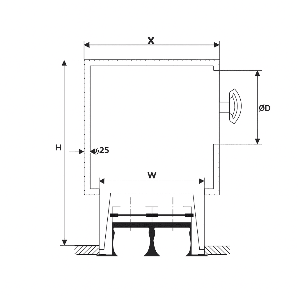
Plenum Size without Insulation
| Number of Slots | D Ø | H | W | X |
|---|---|---|---|---|
| 1 | 150 | 275 | A + 10 | W + 50 |
| 2 | 200 | 275 | A + 10 | W + 50 |
| 3 | 200 | 275 | A + 10 | W + 50 |
| 4 | 250 | 275 | A + 10 | W + 50 |
| 5 | 250 | 275 | A + 10 | W + 50 |
| 6 | 315 | 340 | A + 10 | W + 50 |
| 7 | 315 | 340 | A + 10 | W + 50 |
| 8 | 315 | 340 | A + 10 | W + 50 |
Possible Problems & Solutions
If a noise level problem occurs at the commissioning stage, it is recommended that the following basic procedures are employed to determine if the ATD is responsible.
• Shut down, in rotation, the various plants serving the conditioned space to identify which system is creating the noise.
! Do not be misled by the possible air imbalance created within the conditioned space, i.e. supply only creating noise by air escaping through decoration, etc.
• On the noisy system, check the position of the ATD dampers. If these are properly closed, open the dampers. If the noise level is reduced then damper-generated noise is probably the cause.
! Consider introducing the duct dampers well upstream of the ATD to provide required pressure drop for balancing.
If opening and closing of the ATD does not result in any significant change of noise level, either the noise is entering the conditioned space through some other path, i.e. structure-borne vibration, direct transmission through walls, ceiling, or floor, duct breakout, or is propagating down the duct from another noise source.
! Remove the ATD and the associated damper.
If the noise level reduces, then the source of the problem may well be the ATD and the damper. But if the noise level increases, it is likely that the duct-borne noise is propagating down the system from some upstream source, possible main control damper, primary fans, poorly designed duct junctions, etc. However, should investigation indicate that the noise problem is associated with the ATD / damper / plenum box combination, then consider remedial measures such as:
• Replacing the ATD with one of greater free area or even a larger device.
• Re-design the plenum box (possibly increasing the number of air inlet spigots).
• Increase the number of ATDs.
Cost implications of remedial action should the noise problem occur with an ATD clearly emphasize the importance of total consideration at the design stage to correct selection.
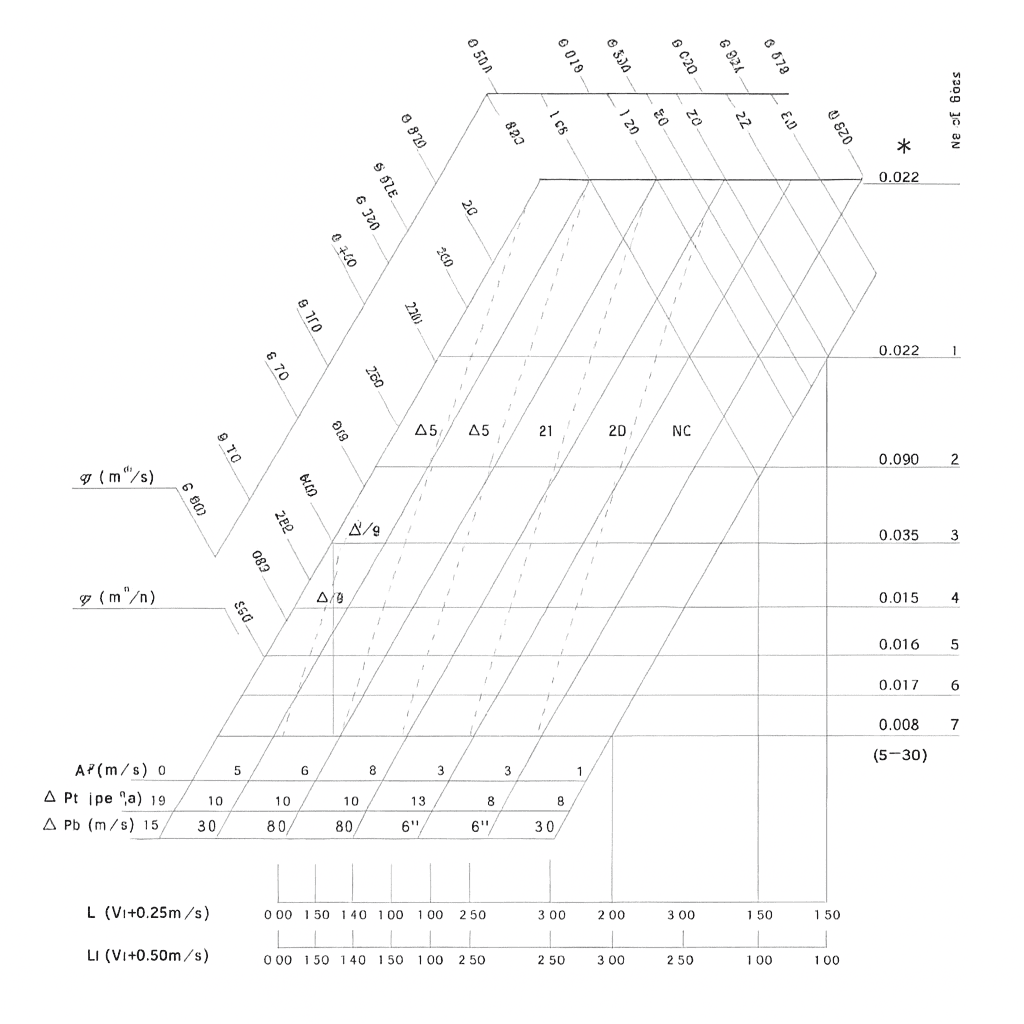
Quick Selection Chart
Correction Charts for other lengths
| L (m) | 1 | 1.5 | 2 | 2.5 | 3 | 4 | 5 | 6 | 8 | 10 |
|---|---|---|---|---|---|---|---|---|---|---|
| Lt (m) | x 1 | x 1.05 | x 1.1 | x 1.1 | x 1.1 | x 1.1 | x 1.15 | x 1.15 | x 1.15 | x 1.15 |
| NC | 0 | +2 | +3 | +4 | +5 | +6 | +7 | +8 | +9 | +10 |
The NC do not take the room absorption into account
Correction Chart for other Vt
| Vc (m/s) | 0.25 | 0.375 | 0.050 | 0.625 |
|---|---|---|---|---|
| Lt x | 1.0 | 0.67 | 0.50 | 0.40 |
Vk × Ak = m³/s
Vk × Ak × 3600 = m³/h