
Bypass Terminal Unit (BPTU)
Description
Alugrid’s Bypass Terminal Units are designed to handle a constant supply of primary air through the inlet while using a diverting damper to bypass a portion of the air into the return plenum.
The damper is controlled directly by a room thermostat, allowing precise adjustments to meet the thermal demands of the occupied space.
The airflow to the conditioned area is regulated using an inlet balancing damper, ensuring consistent pressure requirements.
Additionally, a manual balancing damper in the bypass section can be field-adjusted to align with the discharge duct resistance, maintaining a minimum airflow to the space.
Although these units provide variable air volume to the conditioned space, total fan airflow remains constant, meaning there is no reduction in fan energy consumption.
As a result, bypass units are not considered energy-efficient solutions.
Features
Alugrid’s VAV units feature galvanized sheet steel housing with a thickness of 0.9 mm (21 gauge) and a 1.5 mm galvanized damper blade with a full-round gasket for airtight operation in high-pressure systems.
- The precision die-cast zinc alloy shutter rod rotates within self-lubricating brass bushes, ensuring low-friction operation and long-lasting performance.
- Designed for airtight operation, the units have a leakage factor of under 2% at 750 Pa inlet static pressure, meeting DW 144 Class C standards
- Internal walls are lined with 25 mm mineral fiber acoustic insulation (24 kg/m³), with no loose fibers.
The damper’s tight closure and gasket minimize leakage, complying with DIN 24194 Class 2 standards and carrying E84/UL 723 fire hazard rating.
Rectangular discharge openings are compatible with slip and drive cleat connections, with flanged or other end connections available as options.
Casing
0.9 mm galvanized steel sheet
Double skin available as optional
Damper Blade
1.5 mm galvanized steel sheet
Acoustic Insulation
25 mm thick, 24 kg/m³ mineral fiber
Black acoustic lining meeting UL 181 standard
Bushes
- Brass bush size 12 mm round type
- Powder coating available as optional
Engineering Features
Alugrid’s VAV terminals support Variable Air Volume supplies and offer control options, including Pneumatic, Electrical, and Automated Control Systems (ACS), suitable for various applications.
Pneumatic Control Systems:
These are becoming obsolete, using air pressure from a controller to operate the damper actuator.
Electrical Control Systems:
These send voltage signals from a thermostat to an electric actuator connected to the VAV damper.
Automated Control Systems (ACS):
Similar to electrical systems but integrate building-wide automation, providing graphical and textual data from all VAVs and air handlers.
VAV systems enhance energy efficiency by maintaining constant room temperatures with low-pressure drops.
They are ideal for low to medium-pressure air handling or air conditioning systems & can handle induct pressures up to 750 Pa.
Key Specifications:
Airflow capacity: 21–1900 LPS
Minimum inlet static pressure: 20 Pa
Adjustable minimum air volume: 20%
Design air volume accuracy: ±5% of set point
The design includes bypass port dampers to divert excess airflow and ensures low noise (NC) levels with minimal system pressure drops.
Alugrid’s VAV units are easy to install, relocate, and compatible with various air conditioning systems.
Zero-maintenance models are available, with optional quick-access panels for inspection and servicing.
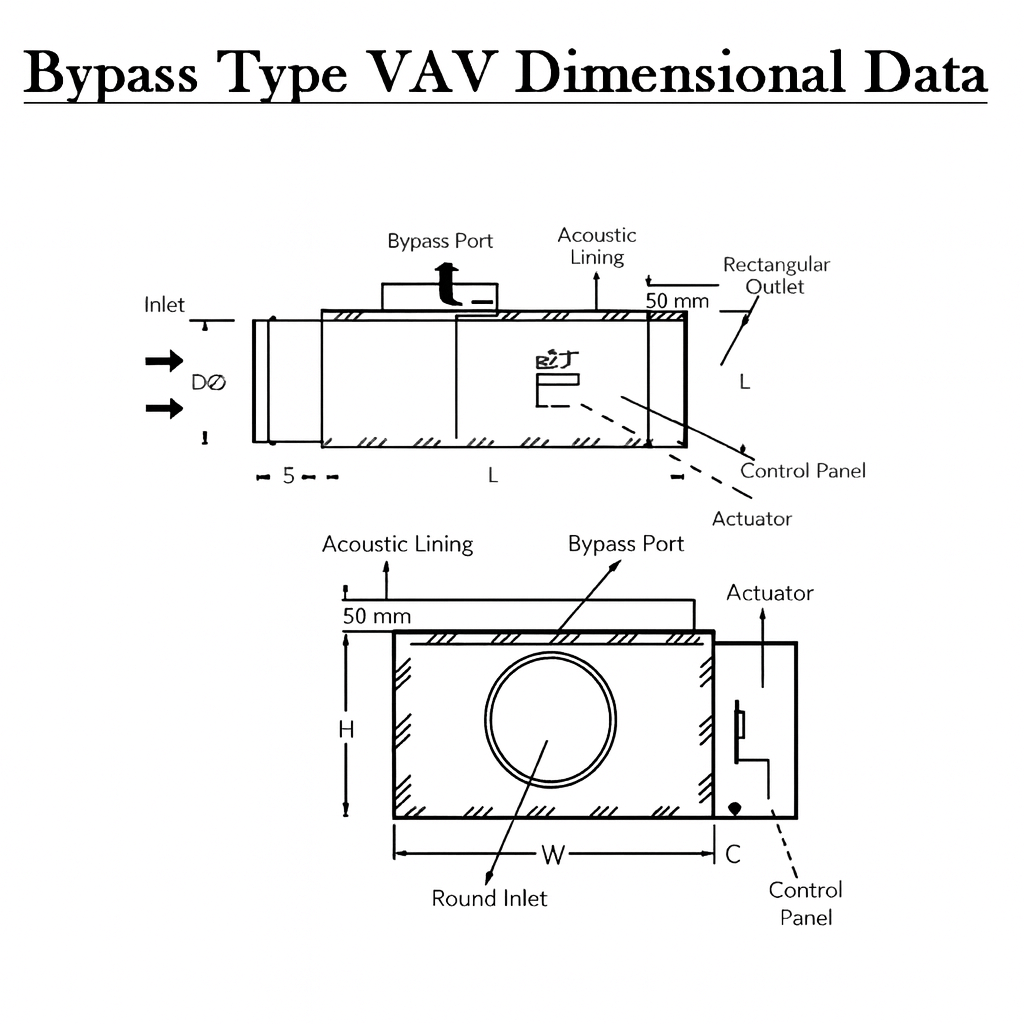
Bypass Type VAV Dimensional Data
Table: Bypass Type VAV Dimensional Data
Model | Air Flow Range (LPS) | Air Flow Range (CFM) | Inlet Dia Ø (mm) | Inlet Ø (inch) | Length (mm) | Height (mm) | Width (mm) | Weight (kg) | Control Panel Height (mm) | Control Panel Depth (mm) |
|---|---|---|---|---|---|---|---|---|---|---|
BPTU–25 | 21–282 | 50–600 | 250 | 10 | 900 | 300 | 350 | 18 | 150 | 100 |
BPTU–32 | 109–379 | 200–800 | 320 | 12 | 1000 | 350 | 400 | 22 | 150 | 100 |
BPTU–40 | 308–650 | 300–1400 | 400 | 16 | 1100 | 400 | 450 | 28 | 200 | 100 |
BPTU–50 | 544–1188 | 1000–2500 | 500 | 20 | 1200 | 450 | 500 | 35 | 200 | 100 |
BPTU–63 | 944–1414 | 2000–3000 | 630 | 24 | 1400 | 500 | 550 | 40 | 200 | 100 |
Performance Notes
Units obtained in accordance with AHRI Standard 880-2011 and ASHRAE Standard 130-1996.
Airflow is given in liters/sec (LPS) and cubic feet/min (CFM).
Blank spaces “–” indicate NC’s less than 20.
“X” indicates minimum static pressure of unit exceeds the minimum operating pressure across the unit.
Minimum static pressure is the pressure loss for the bare unit only at the tabulated flow.
Pressure given in Pascals, Pa and inches of water gauge, in W.G.
NC levels are calculated based on typical attenuation values outlined in Appendix E, AHRI Standard 885-2008, “A Procedure for Estimating Occupied Space Sound Levels in the Application of Air Terminals and Air Outlets.”
Radiated Sound
Based on a 5/8” mineral fiber tile ceiling per AHRI 885-2008 typical attenuation values:
Table: Radiated Sound – Total Deductions
Total Deductions | 125 | 250 | 500 | 1,000 | 2,000 | 4,000 |
|---|---|---|---|---|---|---|
All Sizes | 18 | 19 | 20 | 26 | 31 | 36 |
Radiated Sound
Based on environmental effect, end reflection, flex duct effect, space effect, sound power division and lined duct effect.
Table: Radiated Sound – Environmental Effects
Total Deductions | 125 | 250 | 500 | 1,000 | 2,000 | 4,000 |
|---|---|---|---|---|---|---|
< 400 CFM | 24 | 28 | 39 | 53 | 59 | 40 |
400 – 800 CFM | 27 | 29 | 40 | 51 | 53 | 39 |
> 800 CFM | 29 | 30 | 41 | 51 | 52 | 39 |