Introduction
1 Slot – Flange Type
VERTICAL THROW MODEL (FBD-F)
ALUGRIDX Flowbar Slot Diffuser is designed for high airflow quantities suitable for ceiling applications.
Air pattern can be controlled using pattern controllers, powder-coated black, if required.
Curve is available upon request for 1 Slot Flowbar diffuser.
A 3 Slot Flowbar Diffuser is available upon request.
DIMENSIONS AND DETAILS (1 SLOT)
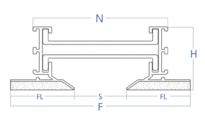
Slot Size | FL | S | N | F | H |
|---|
1 Slot (25 mm) | 41 | 25 | 70 | 107 | 42 |
1 Slot (38 mm) | 48 | 38 | 95 | 134 | 42 |
1 Slot (51 mm) | 54 | 51 | 121 | 159 | 42 |
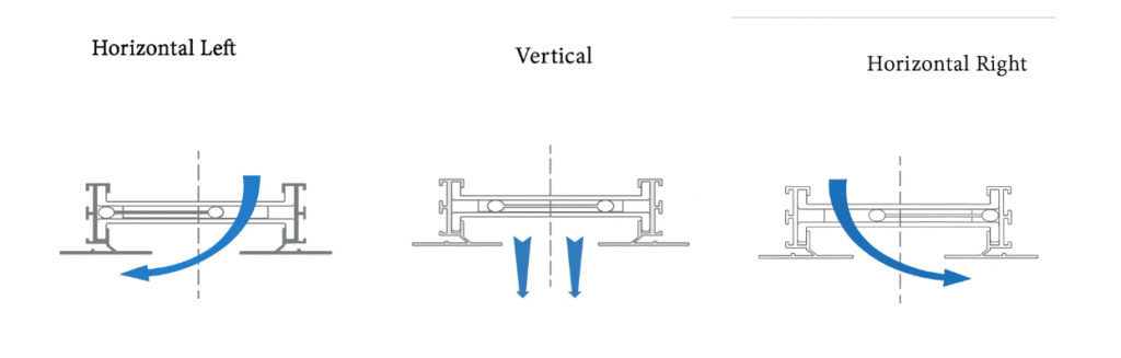
Air Movement
1 Slot – Hidden Frame 45°
VERTICAL THROW MODEL (FBD50-HF)
ALUGRIDX Flowbar Slot Diffuser is designed for high airflow quantities suitable for ceiling applications.
Air pattern can be controlled using pattern controllers, powder-coated black, if required.
DIMENSIONS AND DETAILS (1 SLOT)
Slot Size | FL | S | N | F | H |
|---|
1 Slot (25 mm) | 41 | 25 | 70 | 107 | 42 |
1 Slot (38 mm) | 48 | 38 | 95 | 134 | 42 |
1 Slot (51 mm) | 54 | 51 | 121 | 159 | 42 |
Air Movement
1 Slot – Plaster Hidden Frame 45°
HORIZONTAL THROW MODEL (FBD50-PHF)
ALUGRIDX Flowbar Slot Diffuser Plaster Hidden Frame is designed for high airflow quantities suitable for ceiling applications.
Air pattern can be controlled using pattern controllers, powder-coated black, if required.
DIMENSIONS AND DETAILS (1 SLOT)
Slot Size | FL | S | N | F | H |
|---|
1 Slot (25 mm) | 41 | 25 | 70 | 107 | 42 |
1 Slot (38 mm) | 48 | 38 | 95 | 134 | 42 |
1 Slot (51 mm) | 54 | 51 | 121 | 159 | 42 |
Air Movement
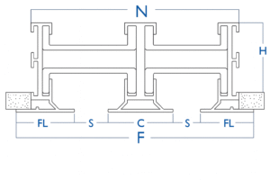
DIMENSIONS AND DETAILS (2 SLOT)
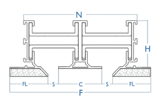
Slot Type | FL | S | C | N | F | H |
|---|
2 Slot (23 mm) | 41 | 23 | 41 | 132 | 170 | 42 |
2 Slot (42 mm) | 48 | 42 | 41 | 182 | 220 | 42 |
2 Slot (62 mm) | 54 | 62 | 41 | 235 | 273 | 42 |
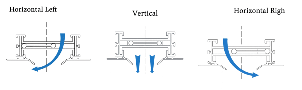
Air Movement
1 Slot – Hidden Frame 90°
VERTICAL THROW MODEL (FBD50-HF)
ALUGRIDX Flowbar Slot Diffuser is designed for high airflow quantities suitable for ceiling applications.
Air pattern can be controlled using pattern controllers, powder-coated black, if required.
Curve is available upon request for 1 Slot Flowbar diffuser.
A 3 Slot Flowbar Diffuser is available upon request.
DIMENSIONS AND DETAILS (1 SLOT)
Slot Size | FL | S | N | F | H |
|---|
1 Slot (25 mm) | 41 | 25 | 70 | 107 | 42 |
1 Slot (38 mm) | 48 | 38 | 95 | 134 | 42 |
1 Slot (51 mm) | 54 | 51 | 121 | 159 | 42 |
Air Movement
2 Slot – Hidden Frame 45°
DIMENSIONS AND DETAILS (2 SLOT)
Slot Type | FL | S | C | N | F | H |
|---|
2 Slot (23 mm) | 41 | 23 | 41 | 132 | 170 | 42 |
2 Slot (42 mm) | 48 | 42 | 41 | 182 | 220 | 42 |
2 Slot (62 mm) | 54 | 62 | 41 | 235 | 273 | 42 |
Air Movement
2 Slot – Hidden Frame 90°
DIMENSIONS AND DETAILS (2 SLOT)
Slot Type | FL | S | C | N | F | H |
|---|
2 Slot (23 mm) | 41 | 23 | 41 | 132 | 170 | 42 |
2 Slot (42 mm) | 48 | 42 | 41 | 182 | 220 | 42 |
2 Slot (62 mm) | 54 | 62 | 41 | 235 | 273 | 42 |
Air Movement
Performance Data
1 Slot
25 mm Slot Width
Parameter | 36 | 58 | 79 | 101 | 122 | 144 | 165 |
|---|
Airflow (l/s) | 36 | 58 | 79 | 101 | 122 | 144 | 165 |
Static Pressure (Pa) | 7 | 18 | 34 | 55 | 81 | 112 | 148 |
NC (Noise Criteria) | <10 | 16 | 26 | 33 | 39 | 44 | 49 |
Throw (m) | 1.5–2.5–4.3 | 2.8–4–5.5 | 3.8–4.5–6.5 | 4.3–5.3–7.3 | 4.5–5.8–8.3 | 5.3–6–8.8 | 5.5–6.8–9.5 |
38 mm Slot Width
Parameter | 43 | 65 | 86 | 108 | 129 | 151 | 173 |
|---|
Airflow (l/s) | 43 | 65 | 86 | 108 | 129 | 151 | 173 |
Static Pressure (Pa) | 8 | 18 | 32 | 51 | 73 | 99 | 129 |
NC (Noise Criteria) | <10 | 14 | 24 | 31 | 37 | 42 | 48 |
Throw (m) | 1.8–3–5 | 3–4.3–5.8 | 4–5–6.8 | 4.3–5.5–7.5 | 5–5.8–8.3 | 5.3–6.5–8.8 | 5.5–6.8–9.8 |
51 mm Slot Width
Parameter | 43 | 72 | 101 | 129 | 158 | 187 | 216 |
|---|
Airflow (l/s) | 43 | 72 | 101 | 129 | 158 | 187 | 216 |
Static Pressure (Pa) | 5 | 14 | 28 | 46 | 68 | 95 | 127 |
NC (Noise Criteria) | <10 | 11 | 22 | 30 | 36 | 41 | 46 |
Throw (m) | 1.5–2.8–5 | 2.8–4.3–6 | 4–5.3–7.3 | 5–5.8–8.3 | 5.3–6.5–9.3 | 5.8–7–10 | 6–7.5–10.8 |
2 Slot
23 mm Slot Width
Parameter | 36 | 58 | 79 | 101 | 122 | 144 | 165 |
|---|
Airflow (l/s) | 36 | 58 | 79 | 101 | 122 | 144 | 165 |
Static Pressure (Pa) | 4 | 9 | 20 | 30 | 42 | 51 | 62 |
NC (Noise Criteria) | <10 | <15 | <15 | 25 | 30 | 33 | 38 |
Throw (m) | 1–1.2–2.1 | 1.4–2–2.8 | 1.9–2.3–3.3 | 2.2–2.7–3.6 | 2.3–2.9–4.2 | 2.7–3–4.4 | 2.8–3.4–4.8 |
42 mm Slot Width
Parameter | 43 | 65 | 86 | 108 | 129 | 151 | 173 |
|---|
Airflow (l/s) | 43 | 65 | 86 | 108 | 129 | 151 | 173 |
Static Pressure (Pa) | 4 | 9 | 19 | 23 | 35 | 40 | 52 |
NC (Noise Criteria) | <10 | <15 | <15 | 20 | 30 | 32 | 35 |
Throw (m) | 1–1.5–2.5 | 1.5–2.2–2.9 | 2–2.5–3.4 | 2.2–2.8–3.7 | 2.5–2.9–4.2 | 2.7–3.3–4.4 | 2.8–3.4–4.9 |
62 mm Slot Width
Parameter | 43 | 72 | 101 | 129 | 158 | 187 | 216 |
|---|
Airflow (l/s) | 43 | 72 | 101 | 129 | 158 | 187 | 216 |
Static Pressure (Pa) | 3 | 7 | 14 | 21 | 31 | 38 | 51 |
NC (Noise Criteria) | <10 | <15 | <15 | 18 | 20 | 30 | 35 |
Throw (m) | 1–1.4–2.5 | 1.4–2.2–3 | 2–2.6–3.4 | 2.5–2.9–4.2 | 2.7–3.2–4.7 | 2.9–3.5–5 | 3–3.8–5.4 |
Pressure Loss
Pressure Loss data is applicable under the condition of inlet duct velocities below 4 m/sec.
Isothermal throw values are furnished for terminal velocities of 0.3, 0.5, and 0.8 m/sec.
Throw Corrections
For a 600 mm section, the throw values are 0.72 times those indicated.
For a continuous length of 3000 mm, the throw values increase by 1.7 times the shown values.
For 3600 mm, the multiplier is 1.8 times.
Air Pattern Notes
Provided values are for 1-way air pattern.
For divided airflow, select airflow per direction based on number of slots aimed in that direction (total airflow splits across aimed slots).
Noise Criteria Notes
Each NC value represents the noise criteria curve such that the sound pressure across octave bands (2nd through 7th) will not surpass it.
Measured with room absorption of 10 dB, equivalent to 10¹² Watts, using a 1200 mm section (other lengths require correction — see table A).
Test Conditions
Tests performed without Plenum effect (no pressure or sound influence).
Throw values are based on 1-way slot discharge.
Pressures shown in Pascal (Pa).
Throw values derived from active sections of 1200 mm.
TABLE A — NC Correction with Length
Length (mm) | 600 | 1200 | 1800 | 2400 | 3000 |
|---|
Supply | -3 | 0 | +2 | +3 | +5 |
Return | 0 | +3 | +5 | +6 | +8 |
TABLE B — Throw Correction with Length
Length (mm) | 600 | 1200 | 2400 | 3000 | 3600 |
|---|
Throw Correction | 0.72 | 1 | 1.5 | 1.7 | 1.8 |