
Linear Bar Grilles
Dimension Data
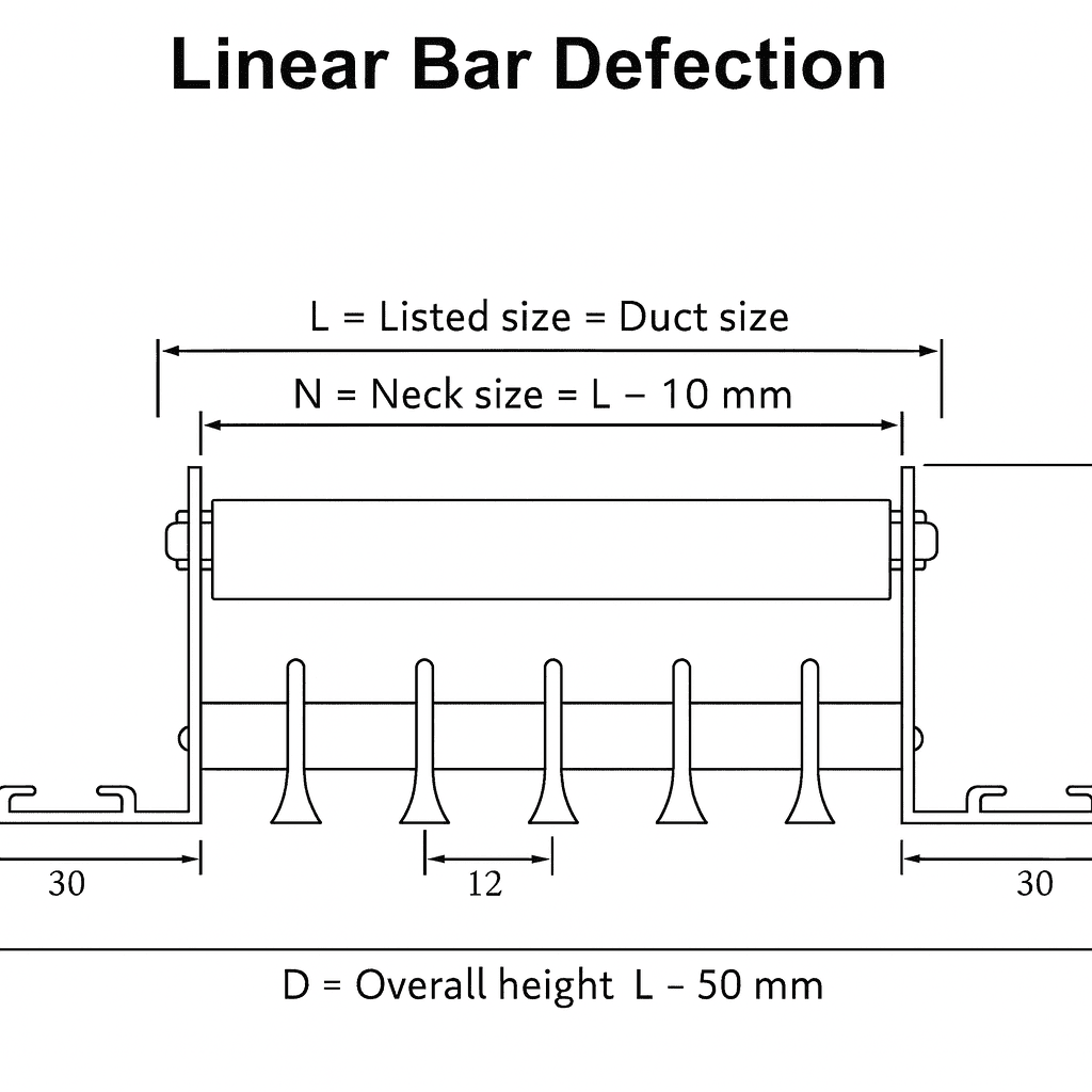
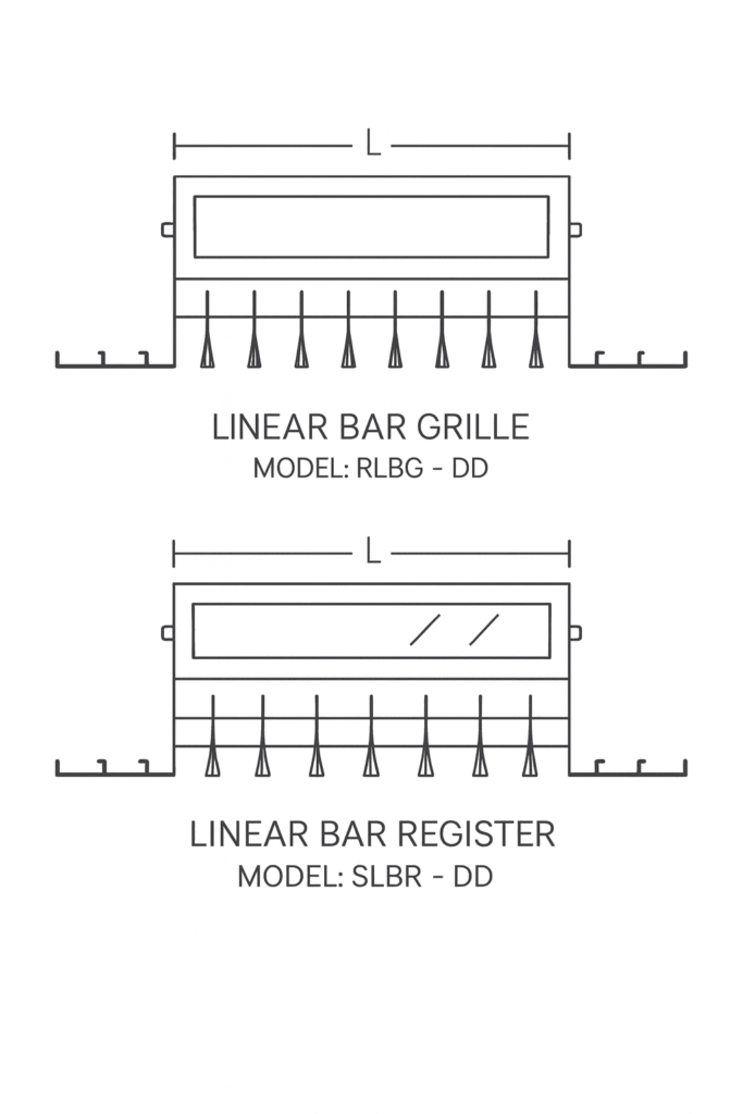
Linear Bar Grille
Description:
Frame and face bars are of high quality extruded aluminium profiled construction with the advantages of corrosion resistance and rigidity.
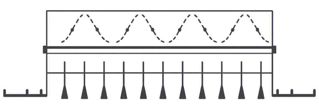
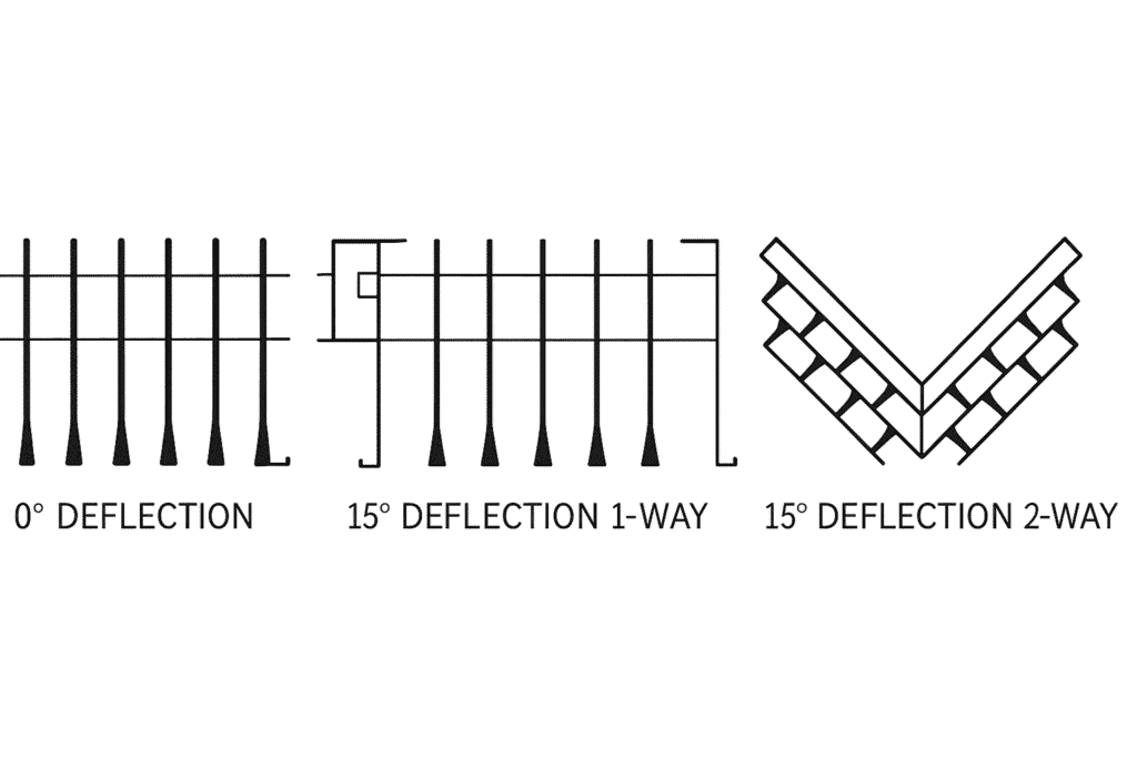
Horizontal face bars with 0°, 15°-1 way throw and 15°-2 way throw are fixed rigidly to the frame with 8 mm pipes.
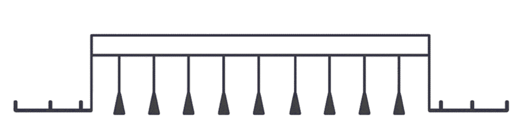
Vertical aluminium aerofoil blades are fixed at the rear side of the frame by nylon bushes.
These blades can be adjusted manually and individually in the vertical plane to obtain optimum air distribution.
For perfect unbroken appearance of continuous runs, alignment strips are provided with no additional cost.
Total structure is manufactured by mechanical assembly, assuring rigidity and to maintain straight line appearance.
Supplied with C-clamps for concealed fixing.
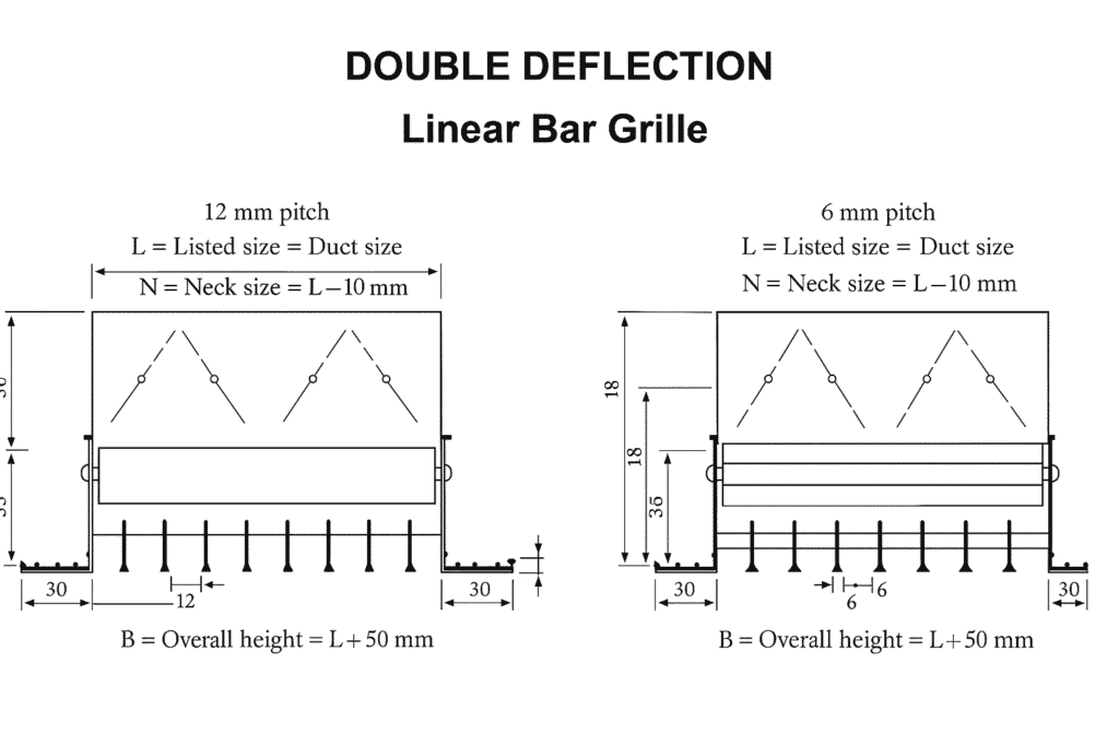
Description:
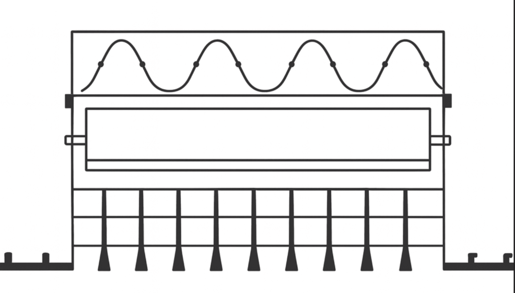
Frame and face bars are of high quality extruded aluminium profiled construction with the advantages of corrosion resistance and rigidity.
Horizontal face bars with 0°, 15°-1 way throw and 15°-2 way throw are fixed rigidly to the frame with 8 mm pipes.
Vertical aluminium aerofoil blades are fixed at the rear side of the frame by nylon bushes. These blades can be adjusted manually and individually in the vertical plane to obtain optimum air distribution.
Grilles are fixed rigidly with an opposed blade damper by grippers to ensure positive control over the air stream. Damper blades can be screw operated from the face opening of the grille.
Provided with alignment strip for continuous appearance. Foam gasket is sealed around the back of the frame to avoid air leakage.
Supplied with C-clamps for concealed fixing.
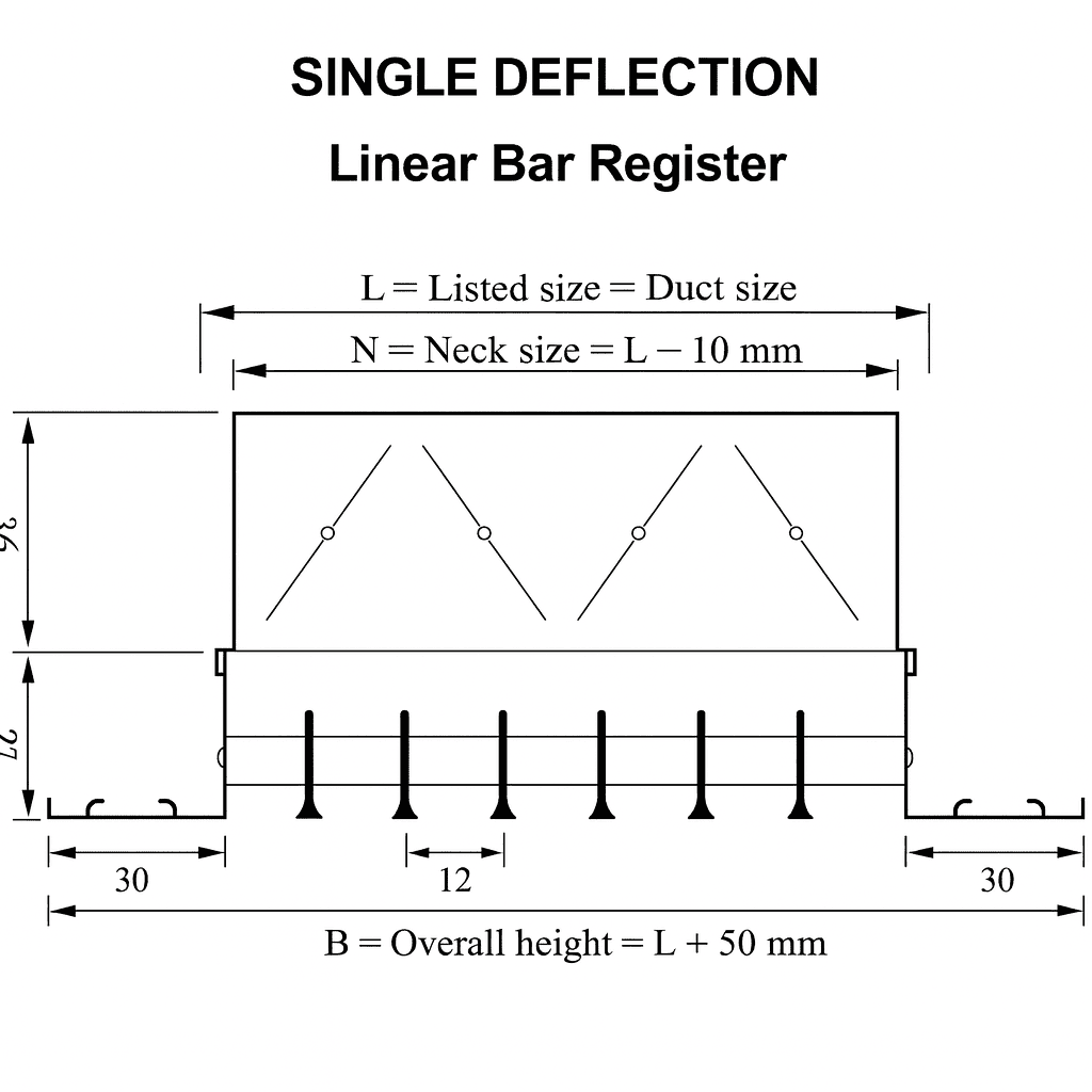
Linear Bar Register
Description:
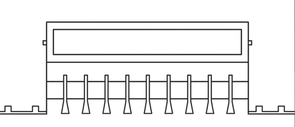
Frame and face bars are of high quality extruded aluminium profiled construction with the advantages of corrosion resistance and rigidity.
Horizontal face bars with 0°, 15°-1 way throw and 15°-2 way throw are fixed rigidly to the frame with 8 mm pipes.
Grilles are fixed rigidly with opposed blade damper by grippers. This ensures positive control over the air stream. Damper blades can be screw operated from the face opening.
For perfect unbroken appearance of continuous runs, alignment strips are provided with no additional cost.
Foam gasket is sealed around the back of the frame as option to avoid air leakage.
Supplied with C-clamps for concealed fixing.
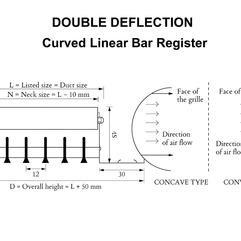
Description:
Frame and face bars are of high-quality extruded aluminium profiled construction with the advantages of corrosion resistance and rigidity.
Horizontal face bars with 0°-1 way throw and 15°-2 way throw are fixed rigidly to the frame with 8 mm pipes.
Vertical aluminium aerofoil blades are fixed at the rear side of the frame by nylon bushings.
These blades can be adjusted manually and individually in the vertical plane to obtain optimum air distribution.
Alignment strips are provided at no additional cost for a perfect unbroken appearance of continuous runs.
Curved linear bar grilles are available up to a length of 3 meters with a minimum radius of curvature of 1 meter.
Available without damper. Dampers can be provided to use in plenum boxes as an option.
The foam gasket is sealed around the back of the frame as an option to avoid air leakage.
Supplied with C-clamps for concealed fixing.
Standard application on curved walls.
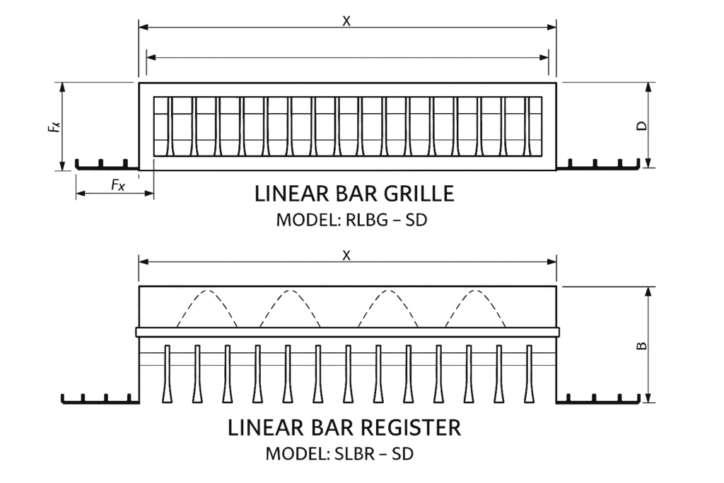
Technical Details & Dimensions
MODEL: RLBG · DD & SLBR · DD
N – Normal Size: L × W
A – (L–10 mm) × (W–10 mm)
B – (L–54 mm) × (W–54 mm)
Fw – Frame Width = 30 mm
Fd – Frame Depth = 45 mm
Bp – Linear Bar Pitch = 6 mm or 12.5 mm
Bt – Bar Thickness
15°–2 Way = 5 mm
15°–1 Way = 3 mm
Dp – Damper Pitch = 25 mm
Dd – Damper Depth = 36 mm
Bp – Pitch of the Vertical Rear Blade = 20 mm
MODEL: RLBG · DD & SLBR · DD
N Normal Size: L × W
A (L–10 mm) × (W–10 mm)
B (L–54 mm) × (W–54 mm)
Fw Frame Width = 30 mm
Fd Frame Depth = 27 mm
Bp Linear Bar Pitch = 6 mm
or 12.5 mm
Bt Bar Thickness
15° · 2 Way = 5 mm
15° · 1 Way = 3 mm
Dp Damper Pitch = 25 mm
Dd Damper Depth = 36 mm
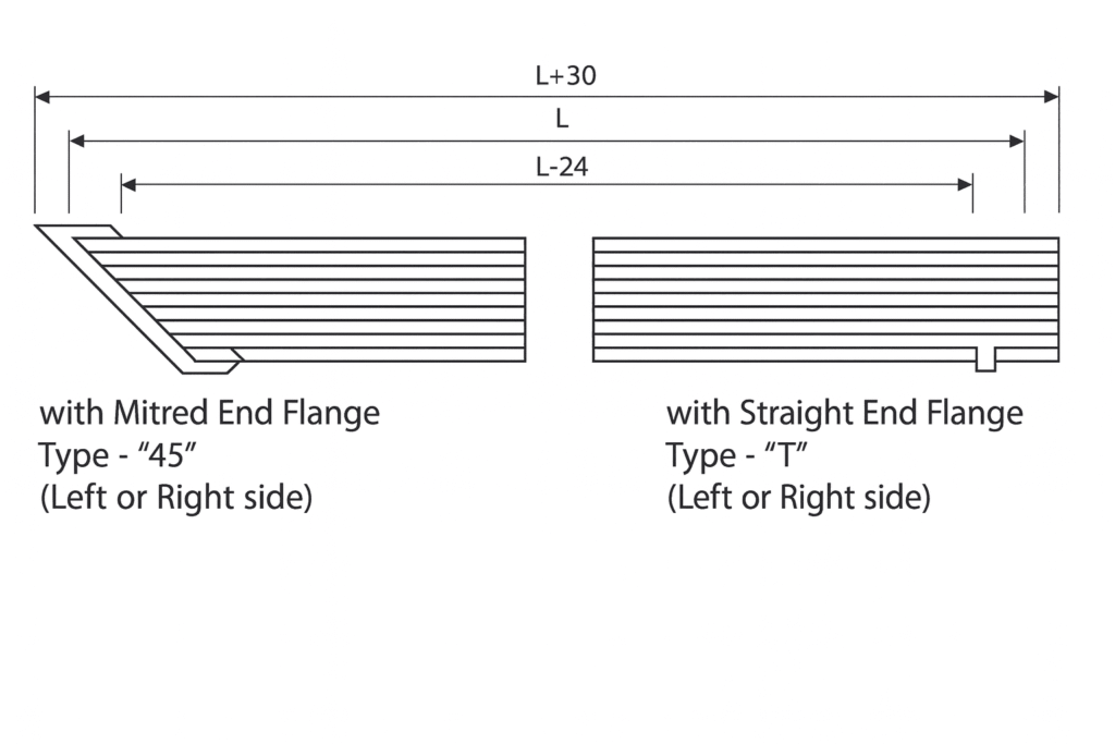
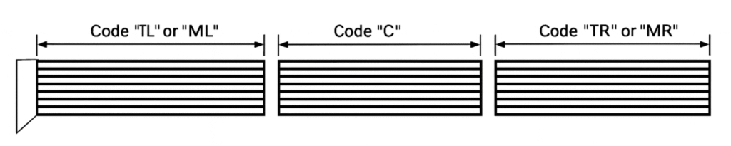
Flange/Assembly Options
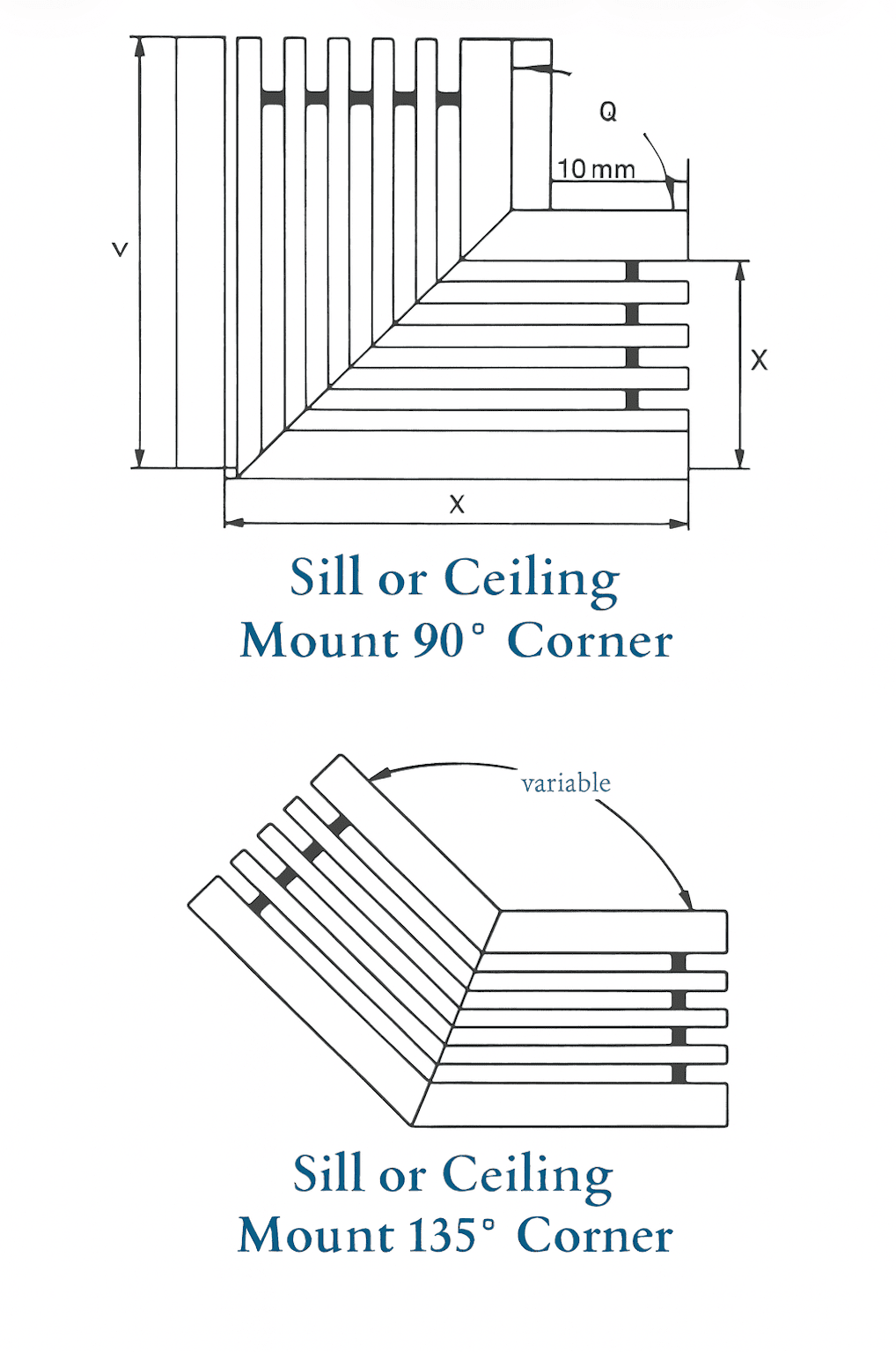
Special horizontal mitered corner available for floor, sill,
and ceiling mounting applications to get an angle greater
than 90° and less than 180°. Available in 0°, 15° one-way
and two-way deflections, and are without dampers.
| W | X | Y | Q |
|---|---|---|---|
| 100 | 300 | 300 | 45° |
| 150 | 600 | 600 | 90° |
| 200 | 800 | 800 | 135° |
| 250 | 1000 | 1000 | |
| 300 | 1200 | 1200 |
Standard 90° horizontal mitered corners are available
for floor, sill, and ceiling mounting in 0°, 15° one-way or
two-way deflection, and are without damper.
Technical Details & Dimensions
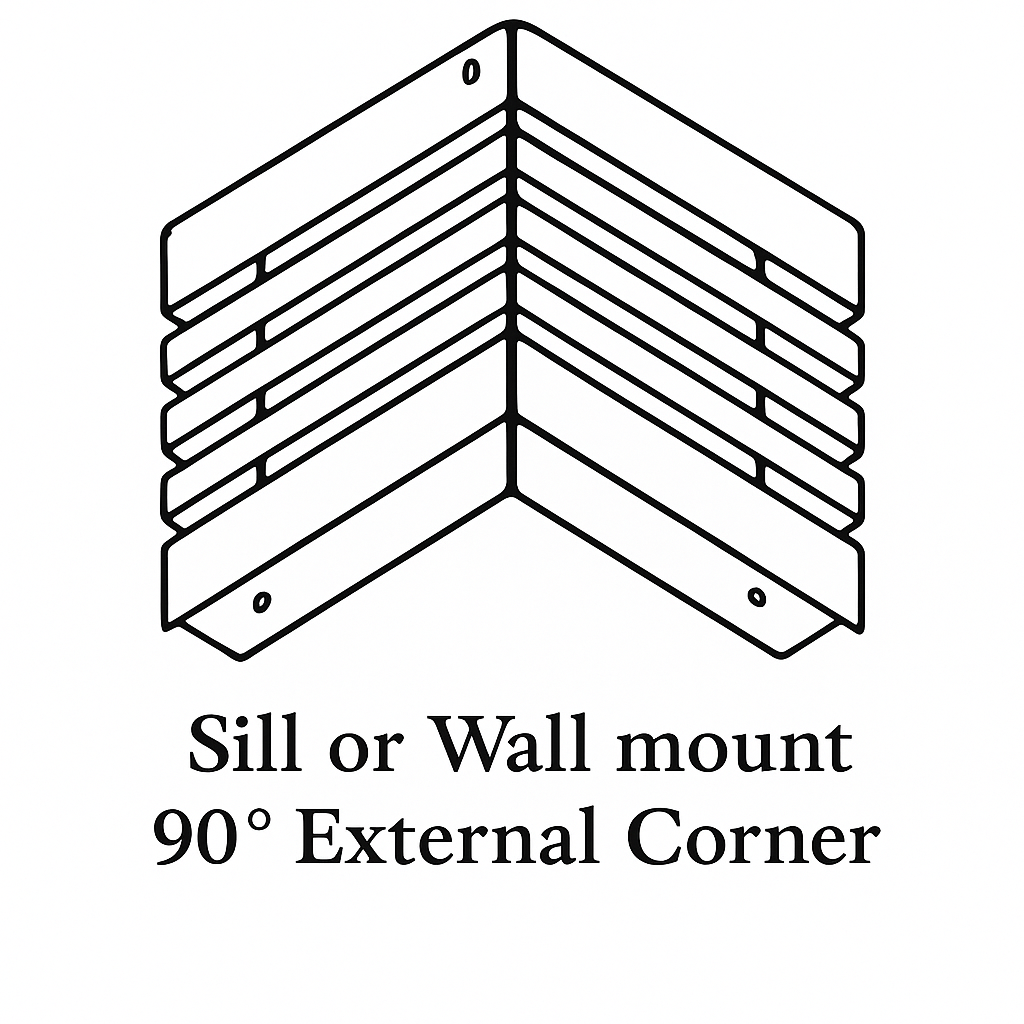
Sill or Wall mount
90° External Corner
Vertical outside mitered corners are available for vertical side wall application at the junction of two outside walls with a standard angle of 90°, available in 0°, 15° one-way and two-way deflections.
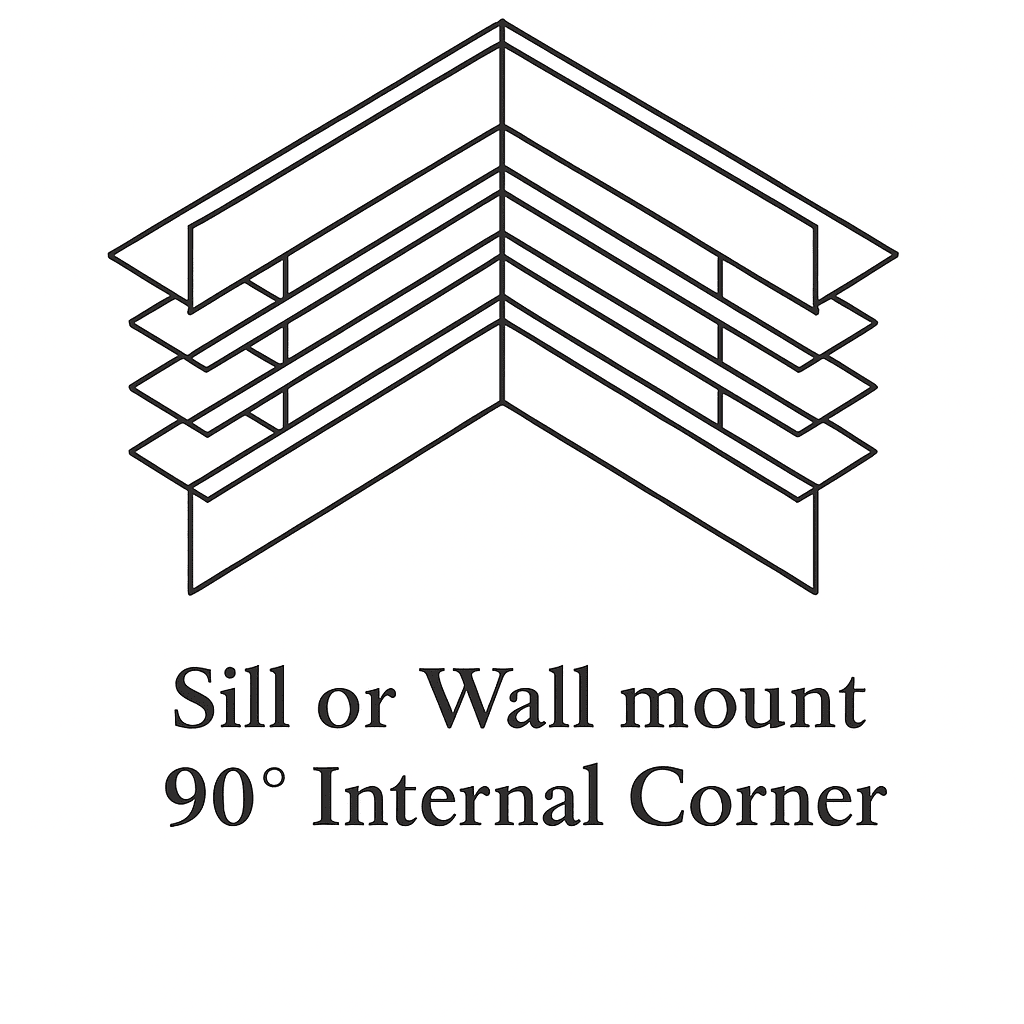
Sill or Wall mount
90° Internal Corner
Vertical inside mitered corners are available for vertical side wall application at the junction of two inside walls with a standard angle of 90°, available in 0°, 15° one-way and two-way deflections.
Standard Bar & Core Styles
MODEL : RLBG – SD
Return Linear Bar Grille with horizontal face 0° deflection or 15° one-way or two-way deflection.
MODEL : RLBR – SD
Return Linear Bar Register same as RLBG-SD but with Opposed Blade Damper.
MODEL : RLBG-DD
Return Linear Bar Grille with fixed horizontal face bar 0° deflection, 15° one-way or two-way deflection and vertical adjustable bars.
MODEL : SLBR-DD
Supply Linear Bar Register same as RLBG-DD but with Opposed Blade Damper.
Engineering & Performance Data
A wide variety of core styles available.
The Core Styles shown can be used with or without border frames.
The linear bar spacing (bar pitch) of 6 mm and 12.5 mm are available only for 0° and 15° one-way deflection, and 12.5 mm bar pitch for 15° two-way deflection.
The internal supporting bars are placed at 300 mm distance from each other.
NOTES ON SELECTION
The throw is normally selected up to 3/4 of the room length.
For a large air volume where the throw is more than 3/4 of the room length, distributing the air volume over several outlets will reduce the throw.
The drop of the selected outlet plus 1.8 m is the minimum grille or register height from the floor.
From the quick selection diagram, the size of the grille/register can be selected taking into account the throw, velocity, pressure loss, and noise level of the grille.
For supply grilles and registers, airflow, air throw, and spread characteristics are the principal factors for the selection.
In order to obtain long air throw and narrow air pattern, use the deflections between 0° and 15° deflection angle.
For shorter throw and wide air pattern, use 15° two-way angle linear bar grilles.
Performance data shown in the selection charts on the following pages is based on 0°, 15° one-way, and 15° two-way linear bar grilles having a width of 50 mm to 300 mm linear bar grilles and of 1 m lengths.
When the volume control damper is partially closed for balancing purposes or final airflow control, in addition to pressure drop and sound correction, the throw pattern will be reduced between 10% and 18% depending upon the amount of throttling. The pressure drop will increase accordingly. The sound level of a supply grille is in direct ratio to the velocity of the air pressure through it.
Air passing through a properly selected air terminal device will not add any appreciable noise to the sound level of the existing system.
In order for a new air-conditioning system to perform to the designer’s plans and specifications, it must be properly balanced to deliver the required amount of air through each air terminal device.
Correct ceiling heights must be observed in order to prevent air stream from dropping into the occupied zone which is generally about 1.8 m above floor level.
Linear Bar Grille
LINEAR BAR GRILLE MODELS: SLBR / RLBG
Ak Selection table for 0° and 15° one-way
L × W (mm) | Bar Pitch 6 mm / Ak m² | Bar Pitch 12.6 mm / Ak m² |
|---|---|---|
1000 × 50 | 0.020 | 0.029 |
1000 × 100 | 0.041 | 0.059 |
1000 × 150 | 0.063 | 0.093 |
1000 × 200 | 0.090 | 0.129 |
1000 × 250 | 0.115 | 0.164 |
1000 × 300 | 0.144 | 0.199 |
Ak Selection table for 0° and 15° two-way
L × W (mm) | Bar Pitch 6 mm / Ak m² | Bar Pitch 12.6 mm / Ak m² |
|---|---|---|
1000 × 50 | – | 0.029 |
1000 × 100 | – | 0.059 |
1000 × 150 | – | 0.093 |
1000 × 200 | – | 0.129 |
1000 × 250 | – | 0.164 |
1000 × 300 | – | 0.199 |
CORRECTION FACTORS:
a) Correction of throw without ceiling effect:
Distance between grille and ceiling > 0.9 m (3 ft.) × Tᵥ value by 0.7
b) Correction for damper adjustment
% OPEN | Pt | NR |
|---|---|---|
100 | × 1.0 | +0 |
50 | × 2.5 | +10 |
25 | × 6.0 | +20 |
c) Correction of rear vertical blade deflection
Deflection | Pt | Vk | Lᵥ | NR |
|---|---|---|---|---|
22° | × 1.3 | × 1.15 | × 0.77 | −3 |
d) Correction of throw for different values of Vt
Vt (m/sec) | Vt (FPM) | Lt |
|---|---|---|
0.25 | 50 | × 1 |
0.5 | 100 | × 0.5 |
0.625 | 125 | × 0.4 |
e) Correction of rear vertical blade reflection
Length (m) | 1 | 1.5 | 2 | 2.5 | 3 | 4 | 5 | 6 |
|---|---|---|---|---|---|---|---|---|
T (m) | ×1 | ×1.05 | ×1.1 | ×1.1 | ×1.1 | ×1.1 | ×1.1 | ×1.15 |
NR | +1 | +2 | +3 | +4 | +5 | +6 | +7 |